MOST OF WHAT YOU WISH YOU KNEW ABOUT COILS OF WIRE BUT WERE AFRAID TO ASK

If you are a novice electronic constructor, you will become familiar with common electronic components. Resistors, capacitors, transistors, diodes, LEDs, integrated circuits. These are the fodder for countless learning projects, and will light up the breadboards of many a Raspberry Pi or Arduino owner.
There is a glaring omission in that list, the inductor. True, it’s not a component with much application in simple analogue or logic circuits, and it’s also a bit more expensive than other passive components. But this omission creates a knowledge gap with respect to inductors, a tendency for their use to be thought of as something of a black art, and a trepidation surrounding their use in kits and projects.
We think this is a shame, so here follows an introduction to inductors for the inductor novice, an attempt to demystify them and encourage you to look at them afresh if you have always steered clear of them.
Inductor basics
If you consider an electrical conductor with a current flowing through it, Oersted’s Law tells us that current will create a magnetic field around the conductor. If the current flowing through the conductor changes, Lenz’s Law tells us that as it causes the magnetic field to change, that in turn induces a current in the conductor which opposes the current flowing into it. This property is referred to as the inductance.
Inductance is measured in Henries, best described in a straight cut-and-paste from the encyclopedia that you have no requirement to memorise: “The inductance of an electric circuit is one henry when an electric current that is changing at one ampere per second results in an electromotive force of one volt across the inductor“. In practice a henry is a rather large unit, so it is more likely that you will encounter millihenries, microhenries, or even nanohenries.

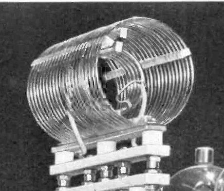
Of course, a single conductor, or piece of wire, doesn’t have much ability to create magnetic field, so doesn’t have much inductance. You can increase the inductance by increasing the length of the conductor, but since you will soon run out of space for very long pieces of wire it is normal for all but the tiniest inductors to have that long length of wire wound in a coil, and round a core made from a material with a higher magnetic permeability than air. Thus the schematic symbol for an inductor is a representation of a coil of wire.
So we’ve dealt with what an inductor is. How about what it does? Where will you use one, and how will it be used?
If you are an electronic experimenter or constructor you are most likely to encounter an inductor in a DC filter, a buck/boost inverter, as a transformer, or if radio is your thing, in a tuned circuit or RF filter. They are not restricted to this selection, but considering these cases should serve to demystify inductors and encourage you to give them another look.
Inductors as DC filters

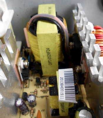
Have you ever opened up a switching power supply, perhaps an ATX model from a PC? Of course you have, you’re a Hackaday reader! If you examined the components, you’ll have noticed a bunch of inductors with coils of thick enamel-covered copper wire next to where the DC cables emerge to power your computer. These serve alongside the smoothing capacitors as a filter, to remove the high frequencies and leave only the DC in the PSU output.
If you remember the paragraph earlier in which we mentioned that a rapidly changing current causes a changing magnetic field which in turn induces an opposing current you may begin to understand the theory of how these filters work: those induced opposing high frequency currents cancel out the input currents responsible for them, meanwhile the stable DC component causes no change in magnetic field and thus no reverse current and passes through unopposed.
Buck and boost inverters
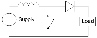
Buck and boost inverters by comparison use the inductor’s ability to store energy as a magnetic field to efficiently convert DC power from one voltage to another. If you pass a current through an inductor you are storing energy in the magnetic field you have created around it, when you stop the current that field collapses and releases its energy by inducing a reverse current in the inductor. This process happens very rapidly so a significant amount of energy can be released in a very short time as a very high voltage spike. Sometimes this spike is a nuisance, for example relay drivers incorporate a diode to safely conduct it away from their transistors, but in a boost converter the inductor is repeatedly pulsed with energy and the resulting spikes diverted through a diode into a reservoir capacitor from which a higher output voltage can be derived.


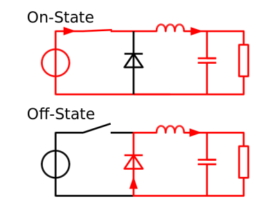
A buck converter by comparison uses the stored energy in an inductor to release a pulse of higher current at lower voltage rather than the high voltage low current spike of the boost converter. The basic circuit is shown on the left, pulses of current create a changing magnetic field in the inductor that induces a reverse voltage which in turn drops the voltage on the load.
Both the example circuits for buck and boost converters shown here are simplified for illustrative purposes. In practice the switch will be replaced by a transistor driven from an oscillator whose pulse width is varied by a feedback circuit connected to the load. This can be a surprisingly simple discrete component circuit, but in both cases there are significant numbers of off-the-shelf integrated circuits designed for the job whose data sheets will provide valuable information about suitable inductor values.
Transformers
If you put a conductor in a changing magnetic field, a current will be induced in it. Lenz’s Law again. This is how dynamos and generators work, and the effect that gives us the reverse current in inductors we’ve been talking about in the last few paragraphs. So if you put one inductor within the changing magnetic field created by another inductor, a current will be induced in the first inductor by that magnetic field. You will have created a transformer, and if we refer to the first inductor as the primary and the second as the secondary the ratio of primary to secondary AC voltage is the same as the ratio between the number of turns of wire in primary and secondary. At a stroke we can change AC voltages from one level to another, and do so while maintaining complete physical isolation between primary and secondary.
Practical transformers are built so that the magnetic fields of the two inductors are as closely coupled as possible. The two coils of wire will occupy the same former and be wound around the same core material, with the aim that all the magnetic flux they create will be contained within that core rather than wasted in the surroundings. The designers of a transformer will have to contend with losses due to induced currents in the core as well as losses due to the resistance of the wire, both producing heat, and with the possibility of the core saturating with magnetic field and the device becoming non-linear at the frequency of operation.
At lower frequencies such as those used by mains electricity the core usually takes the form of iron laminations insulated from their neighbours to reduce induced currents. As the frequency of operation rises the size of core required to avoid magnetic saturation decreases so there is a corresponding decrease in transformer size. This effect is offset by the requirement for higher performance core materials to work at higher frequencies, and for this reason you will see cores made from ferromagnetic ceramics known as ferrites in the high frequency transformers found in switch-mode power supplies or RF applications.

There is another type of transformer you may encounter, the autotransformer. Typically these are used in the inexpensive mains step-up or step-down transformers you can buy over the counter should you wish to use a European 230v appliance on the USA’s 110v, or vice versa. An autotransformer does not have separate windings, instead it has one winding with a third connection somewhere in the middle. Apply an AC voltage between the bottom of the winding and this third connection, and it will induce a voltage at the top of the windings proportional to the ratio between the number of turns up to the third connection, and the whole number of turns. Its operation is very similar to a conventional transformer, however it does not provide a physical isolation between primary and secondary and therefore does not offer isolation from a mains supply.
Inductors in RF circuits
Probably the area of most mystique about inductors surrounds their use in RF circuits. People tempted to try building a radio project balk at the idea of winding their own inductors, and the subject of their design may be responsible for most of that black art we mentioned earlier.

In an RF circuit the designer is most interested in the resonant frequency of a circuit containing inductance and capacitance. In very simple terms if you connect a capacitor and an inductor in parallel and apply a pulse of current to the circuit the energy will “bounce” between magnetic field in the inductor through electric current in the connecting wires to charge stored in the capacitor and back again until resistance losses cause the energy to dissipate, and will do so at a frequency dependent on the inductance and capacitance involved. There is a straightforward formula to calculate resonance that every radio amateur will recite parrot-fashion: “F equals one over two Pi root L C”, but happily there are numerous online resonance calculators if you would prefer to save a little effort.
There is perhaps less need than there might once have been for trepidation at RF inductor design, and in particular at the idea of winding your own inductors. Practical RF inductors in preset values are available off-the-shelf from multiple manufacturers, along with adjustable inductors with threaded ferrite cores that can be moved within the body of the inductor. These components are not as cheap as their resistor and capacitor counterparts, but they do make the RF constructor’s life significantly easier.
Go Forth And Solder
We hope that if you are an inductor novice this article will have given you a basic grounding in the subject and demystified these components for you. As always, there is no substitute for hands-on experience though, so if your curiosity has been aroused on the subject then we’d suggest you get to know the subject by building a few inductor circuits. Start with a simple buck or boost converter based around an off-the-shelf IC, and have a poke around at the voltages and waveforms involved with your oscilloscope. There is a whole world of magnetic goodness out there to be found!


